Lab 5: Week 1 - Getting Started
Purpose
The purpose of this laboratory exercise is to further our understanding of controlling sensors with a computer and using the computer for data acquisition, processing, and control of physical systems.
In this lab you will use thermocouple to measure and record temperature under the control of a Raspberry Pi computer interfaced through the General Purpose Input and Output (GPIO) pins. You will construct the circuit on a breadboard and write a Python script to control the sensor and record data locally. Then, you will connect to the JMU WiFi and construct additional Python code to write data to the cloud where it can be accessed by any device at any time. This will require several cyber security authentication protocols. Finally, you will use the thermocouple sensing system to activate an LED if a critical temperature is reached and send an alert to your cell phone via SMS text messaging.
Learning Goals
The goals of this Lab (all weeks together) are to:
- Review circuit concepts to physically connect measurement hardware to a computer
- Gain experience with General Purpose Input and Output pins (GPIO)
- Become familiar with Python programming used to control sensors and physical systems
- Investigate and evaluate measurement capabilities of a measurement instrument
- Calibrate the instrument
- Control sampling rate
- Calibrate the instrument (and estimate Type B calibration error)
- Determine an estimate of Type A (random) measurement uncertainty
- Write data to a local host computer
- Write data to the Cloud
- Use real-time automated decision making to control physical systems based on incoming data
- Send alerts wirelessly via WiFi and SMS communication protocols
- Report your findings in a formal lab report
This week, we will focus on the basic setup. At the end of the first lab exercise, you should be able to:
- collect temperature measurements using the thermocouple connected to the RPi
Background
Thermocouple sensors are used in a variety of applications to accurately measure temperatures. They are commonly used in industrial manufacturing to control chemical processes, such as fractional distillation of petroleum products and chemical synthesis of pharmaceuticals. They are used in personal computers to control cooling fans. They are used in HVAC systems to regulate temperature in houses, buildings, and large data centers. They are also used to monitor and control kiln temperatures in the firing of ceramics (extremely hot temperatures) and to monitor storage of biological samples and temperature-sensitive biologically active substances (proteins, RNA/DNA, COVID vaccines, etc.)
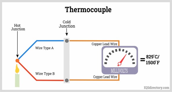
The thermocouple is an extremely reliable instrument. It is based on the “Seebeck Effect”, which is a small voltage that occurs whenever two dissimilar metals are in contact. This voltage will change based on the temperature. When compared to a “reference temperature” at second junction of the two dissimilar metals, an absolute temperature measurement can be obtained. This voltage will be used to provide a measurement of temperature. A diagram of this process is shown in Figure 1.
For our lab, we will need to take this “analog” voltage output and digitize it in order for the signal to be sent to the Raspberry Pi computer. We will use an analog to digital converter to do this.
Methods
Connect the thermocouple sensor to the analog-to-digital converter
The thermocouple sensor will give an output voltage that corresponds to temperature. In order of this output voltage signal to understood by the RPi, it must be converted to a digital signal (the RPi does not accept analog signals, only digital): We must use an Analog-to-Digital converter (A/D board)1.
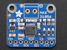
We will use the MAX31856 A/D board. This board provides a reference temperature, converts the analog signal to digital, and and will do the mathematical conversions necessary to calculate temperature before sending the temperature reading to the RPi.
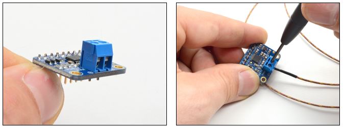
Connect the thermocouple to the MAX31856 A/D board.
Unintuitively, Yellow is (+) and Red is (-). Be sure to get (+) and (-) correct.
Connect the thermocouple to the A/D board like in Figure 2:
Make sure that the RPI is shut down before connecting the thermocouple.
Ask an instructor to get the wiring checked before turning it on.
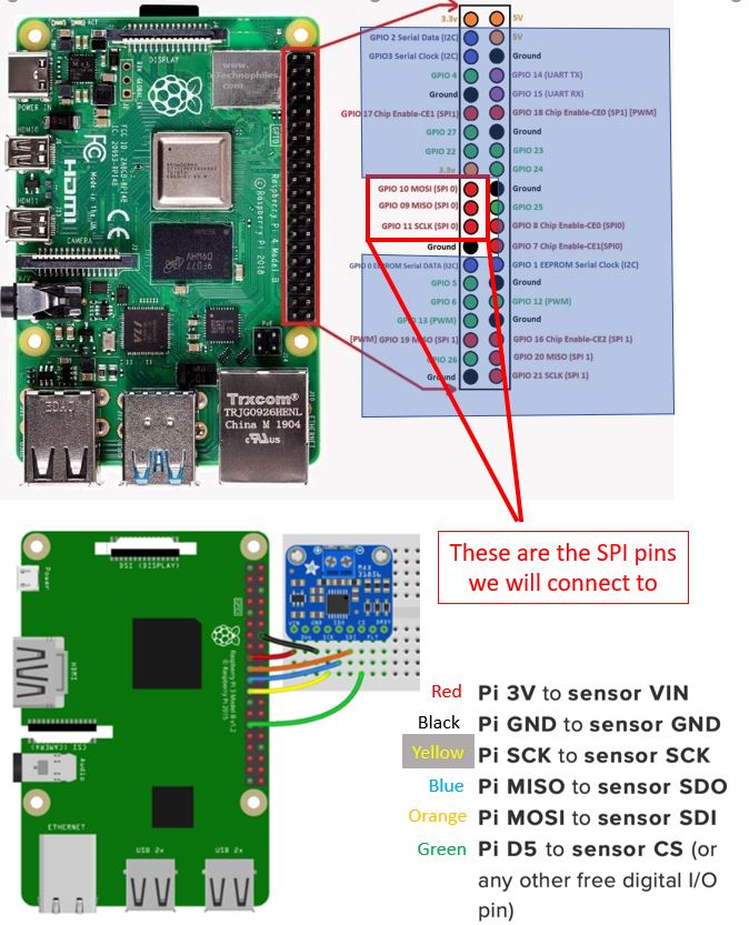
Connect the RPi to the MAX31856 as shown in Figure 3.
Software configuration
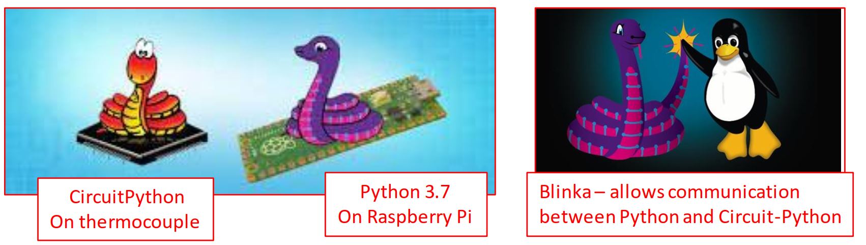
In this lab, we will use Python 3 and CircuitPython. Before writing our scripts, we must ensure the Raspberry Pi is updated and install the necessary python packages.
You will be using the command line to perform these installations and checks.
Linux Terminal: Open a terminal window by clicking on this icon in the upper left of the control bar (Figure 4). This opens the command line, which will be used to enter your commands.
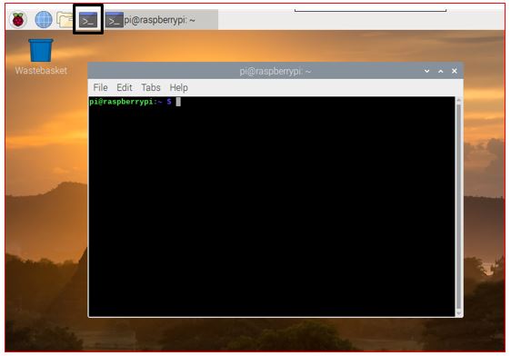
Figure 4: The Terminal window on the Raspberry Pi where to enter system commands Installation Commands:
Run the following commands in your terminal. Type them exactly as shown (or copy them over) and press Enter after each line
# 1. Update the system package list and upgrade current software sudo apt-get update sudo apt-get upgrade -y # 2. Install the virtual environment creator sudo apt-get install python3-venv -y # 3. Create a virtual environment named 'lab5_env' python3 -m venv lab_env # 4. Activate the virtual environment (as root) sudo su source lab_env/bin/activate # CHECK: Your terminal prompt should now start with (lab_env) # 5. Install the Adafruit Python Shell library pip3 install adafruit-python-shell # 6. Install the Raspberry Pi GPIO pip3 install RPi.GPIONoteHelpful definitionssudo: super user do, grants temporary admin rights. Anything executed withsudocan have serious consequences as system files are being changed.apt-get: package manager for linus, which is used to install and maintain new softwareapt-get update:aptchecks for updates of installed software on the internetapt-get upgrade:aptfetches and installs any available system updatesvirtual environment: A self-contained directory that contains a specific Python installation. It prevents conflicts between different projects. It is used to keep of lab libraries separate from the system-wide Python installation. This is good practice, becausepip– the Python package manager – does not check for conflicts between installed python libraries. This means installing Python packages viapiporpip3can break the entire Python installation.
Software Connection: Blinka
The MAX31856 uses CircuitPython, but the RPi runs standard Python 3. To bridge this gap, we use a library called Blinka. Blinka translates the hardware API2 calls.
In order to be able to communicate between the RPi and MAX31865, we will need to install a package called Blinka (Figure 5) to connect the two systems.
Ensure your terminal is open and your virtual environment is active (look for (lab_env)).
If you have closed the terminal and you open another one, you will have to redo the activation step:
sudo su
source lab_env/bin/activate
Download the blinka installation script: Type the following command (it is one long line):
wget https://raw.githubusercontent.com/adafruit/Raspberry-Pi-Installer-Scripts/main/raspi-blinka.pyNoteHelpful terminologywgetis a command to download (get) a file from the web.
So the next two commands, will istall the python-shell and then download a python script to install
blinka.Run the script (make sure you activate the virtual env as sudo)
python3 raspi-blinka.pyNoteNote: If prompted to reboot, allow the system to reboot. After rebooting, remember to reactivate your environment:
source lab_env/bin/activateSoftware connection cest (make sure you activate the virtual env as sudo)
Download the a test program for blinka from my GitHub using
wgetand run the program from the command line.wget https://raw.githubusercontent.com/TobGerken/ISAT300/main/LabCode/blinka-test.py python3 blinka-test.pyThis is how the test program looks:
import board
import digitalio
import busio

print("Hello blinka!")

# Try to great a Digital input
pin = digitalio.DigitalInOut(board.D4)
print("Digital IO ok!")

# Try to create an I2C device
i2c = busio.I2C(board.SCL, board.SDA)
print("I2C ok!")

# Try to create an SPI device
spi = busio.SPI(board.SCLK, board.MOSI, board.MISO)
print("SPI ok!")

print("done!")
If everything is working correctly, you should see the below output printed to the terminal
Hello Blinka
Digital IO ok!
I2C ok!
SPI ok!
done!
Software Connection: MAX31856 Library
The MAX31856 is more than just an analog to digital converter. The chips on this small circuit board will also provide a reference temperature for the thermocouple and are pre-programmed to convert the voltage signal into a temperature reading.
Adafruit (the company that makes this board) has also provided Python packages that we will need to install on the RPi to make the system work.
In the
terminaland execute the below command to install the MAX31856sudo su source lab_env/bin/activate pip3 install adafruit-circuitpython-max31856
Thermocouple Python Interface
It it is good practice to
- create a dedicated folder for your work, where you save all files that belong to a given project. This means e.g. a folder for ISAT300 that contains subfolders for each lab.
- save all files to disk with sensible names
- use typical file extensions, such as
<filename>.pyfor Python files.
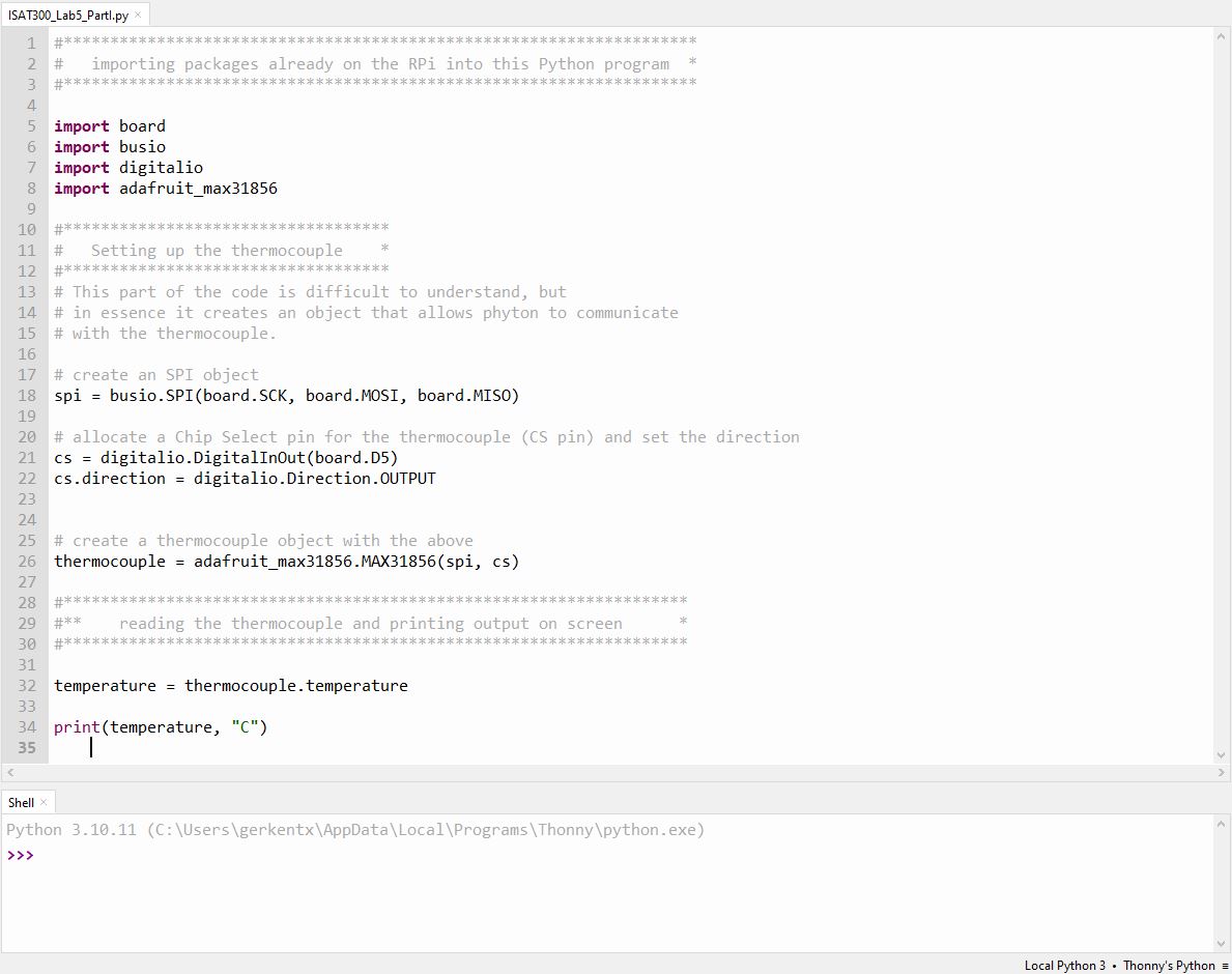
Open the Thonny IDE and obtain the Lab 5 StarterCode from my GitHub:
Complete the missing lines so that the code matches the image below
Before running the code, you must configure Thonny to use your virtual environment. Go to Tools \(\rightarrow\) Options and select the Interpreter tab. Near the dropdown (under Python Executable) click the 3 dots, a window opens, navigate to your virtual environment, and select the python3 file located inside the lab_env/bin/ directory. Click OK, then run your code.
If the above is confusing, there is another way. Because our required libraries are installed in a virtual environment, you could only use Thonny as a text editor. To run your code, open a terminal window, ensure your virtual environment is activated (you should see (lab_env) at the start of your prompt), and run the script by typing: python3 your_script_name.py
Code definitions
Import board: CircuitPython module to provide access to board specific pinsImport busio: Handles SPI3 communicationdigitalio: CircuitPython module to control the input/output for our Chip Select pin- Creating the object
thermocoupleallows python to query the temperature from the thermocouple object by accessing thethermocouple.temperatureattribute, which provides the thermocouple temperature in \(^o\)C.
Unit Conversion Challenge
The default output is in Celsius.
Add the following line to the end of your script to convert it to Fahrenheit:
print(str(temperature * 9 / 5 + 32), "F")Acknowledgements
This Lab was prepared by Dr. Chris Bachmann. Special thanks to Joe Rudmin for obtaining necessary supplies and facilitating the lab setup.
| Revision | Description | Author |
|---|---|---|
| 2024-03-01 | Post lab updates for error fixes and tips | Tobias Gerken |
| 2024-02-23 (S24) | Updated to Web, changes to sample code and images | Tobias Gerken |
| Initial Version | Chris Bachmann |
Footnotes
A/D Converter: A system that converts an analog signal (like a continuous voltage) into a digital signal (1s and 0s) that a computer can process.↩︎
API (Application Programming Interface): A set of protocols that allows different software components to talk to each other.↩︎
SPI (Serial Peripheral Interface): A high-speed, 4-wire communication protocol used for short distances↩︎