Lab 4: Part 2 - Measuring Velocity with an Ultrasonic Sensor
Purpose
Autonomous Vehicles (AV’s) rely heavily on the use of ultrasonic sensors for proximity data and collision avoidance. The purpose of this laboratory exercise is to become familiar with using a computer to control a physical systems based on incoming sensor data. In this lab you will activate an LED when an object comes too close to an ultrasonic sensor. You will also re-program the system to measure velocity.
Learning Goals
The goals of this Lab are to:
- Review circuit concepts to physically connect measurement hardware to a computer
- Gain experience with General Purpose Input and Output pins (GPIO)
- Become familiar with Python programming used to control sensors and physical systems
- Finalize Calibration, Max/Min, Sampling Rate, and Uncertainty measurements
- Use the incoming data to make decisions and activate an external device
- Report your findings in a formal lab report
Background
Ultrasonic sensors are on modern automobiles for collision avoidance and autonomous driving. Accurate, reliable distance measurements are essential in these applications. In part II of this lab, the computer will be programmed to send an alert to the operator and activate an LED if an object comes too close to the sensor. This will be done to simulate Autonomous Vehicle applications of ultrasonic sensors that are used in collision avoidance and navigation by activating steering and braking systems.
Materials
- LED
- 1 resistor (~500 Ohm)
- Breadboard
- Connecting wires
- Ultrasonic Sensor Setup from Part I
Procedure
Re-connect the Ultrasonic Sensor as it was for Part I of this lab. After the Ultrasonic Sensor is re-connected and tested, we can add the LED circuit and addition lines of code to our Python program. You may also use this lab period to finish taking your measurements from part I of the lab.
Use the circuit diagram on the following page to connect the LED to the Raspberry Pi. We will use the common ground on the negative terminal of the LED and a GPIO pin for the positive side. This will allow us to control the voltage (on/off) and thus turn the LED on or off based on the incoming ultrasonic data.
LED’s operate in one direction only; you must hook up the (+) and (-) correctly!
Harware connection - Physical connection for the LED
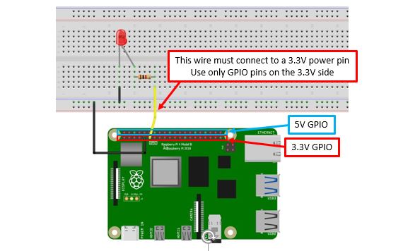
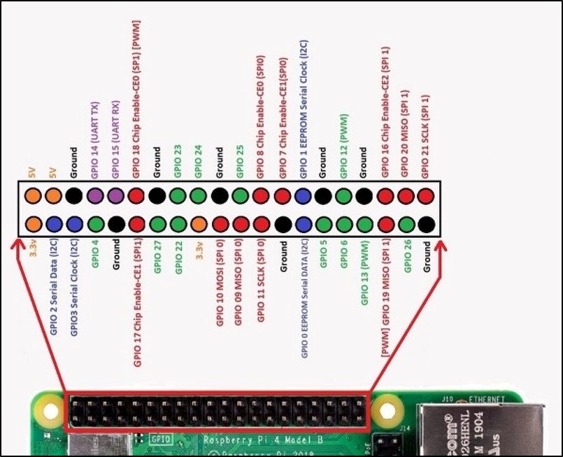
Connect the LED to the RPi as shown in the diagram above. Use different locations on the breadboard to accommodate the ultrasonic sensor, as needed. GPIO pinout is provided below for reference.
Software connection
It is a good idea make a copy of your program so that you can go back to the program from Week 1. In general, I recommend to make frequent saves/ copies of your programs and data.
You will need to adjust several lines of code to the Python program you are using for the ultrasonic sensor and add a few new lines of code as well for this to work properly. Do this AFTER you have finished your measurements for part I of the lab.
Open the ultrasound Python code in Thonny and modify the code in the appropriate locations within the program to:
- control the LED so that the light is normally OFF
- but turns ON (and stays on) when an object is within 2” of the sensor
- Make sure the LED turns OFF if the object is removed.
The below lines are the only lines that you have to add to your code.
You will have to decide on the correct locations within the python program!
GPIO_LED = 17   #
GPIO.setup(GPIO_LED, GPIO.OUT)
if (dist < 5):
       GPIO.output(GPIO_LED, GPIO.HIGH)
       print (“WARNING!!!!”)
else:
GPIO.output(GPIO_LED, GPIO.LOW)- Use
GPIO_LEDto specify the pin YOU physically connected the LED to. - Set the target distance with:
(dist < 5) - Understand what the
if-statement does. What is the meaning ofGPIO.HIGHandGPIO.LOW?
Adjust the sampling loop to give you enough time to test your system (i.e. – you can increase the number of samples so that it runs for quite a long time). You don’t need to write this data to a file either, so comment out the code that calls for data to be written in the .csv file.
Deliverables
Make sure that you have completed all the deliverables for the first part of the lab!
Calibration
In Part 1, you were asked to plot a linear trend on your test measurements. Based on these results, implement a linear calibration (form: \(y = ax + b\)) for your distance measurement.
dist_uncalibrated = distance()
dist = <your calibration equation>
Deliverable for Part 2
Modify the existing Python code to calculate the velocity of an object. Remember that
\(\text{velocity} = \frac{\Delta \text{distance}}{\Delta \text{time}}\)
You already have the distance measurement and you should know the time between successive measurements. Combining these will create an ultrasonic speed sensor. With some additional coding, you can get direct the Pi to make two success distance measurements and record the time between them.
\(\text{Velocity (m/s)} = \frac{\Delta \text{distance}}{\Delta \text{time}} = \frac{\text{(Distance 2 - Distance 1)}}{\text{(Time 2 – Time 1)}}\)
Then, design an experiment using only readily available materials in the lab to ’calibrate’ your speed sensor and show that it is accurately measuring velocity.
Extra Credit Challenge:
Re-program the sensor one more step to measure acceleration. Prove that your sensor is working properly by confirming that Acceleration due to Gravity is 9.8 \(m\,s^{-2}\).
Lab 4 Deliverables
You will submit a joint lab report after completing both parts. Details are found on the lab 4 overview page
Acknowledgements
This Lab was prepared by Dr. Chris Bachmann. Special thanks to Joe Rudmin for obtaining necessary supplies and facilitating the lab setup.
| Revision | Description | Author |
|---|---|---|
| 2026-02-27 (S26) | Added calibration | Tobias Gerken |
| 2025-02-28 (S25) | Moved deliverables to overview page | Tobias Gerken |
| 2024-02 (S24) | Updated to Web | Tobias Gerken |
| Initial Version | Chris Bachmann |