Lab 0: Getting Started
We learn through play
Purpose
You are typically expected to read and understand the lab description before coming to the lab. There is also a weekly Pre-Lab-quiz on Canvas.
For this week, we are just getting started. So just follow along.
Motivation
The purpose of this lab is to become familiar with some common electronics components such as bread boards, power supplies and resistors and to gain experience using a common electronics measurement tool, the digital multimeter (DMM).
We are also introducing the Raspberry Pi computer this week. Soon, your Pi will be used to conduct measurements and you will need to know how to operate and program it.
Building electronic circuits and using small computers for prototyping systems are important skills that you might encounter in your professional career (think Internet of things - IoT).
Learning Goals
The goals of this lab are to:
- Review circuit concepts of resistance, voltage and current that you learned in ISAT 152
- Gain experience using a breadboard and digital multimeter (DMM)
- Gain experience constructing simple circuits on a breadboard
- Measure the behavior of resistors in series vs. parallel
- Learn now to use the Raspberry Pi
- Understand that the Raspberry Pi can be use to control a physical system
- i.e. make an LED blink
You will encounter the Raspberry Pi, breadboards, and the DMM in many labs so learning how to use them now will make things easier later on.
At the same time, no worries, there is going to be lots of opportunities for practice.
Background
This lab consists of two connected activities that will help you acclimatize to the labs.
We will do a short activity to get started with breadboards and the digital multimeter you will be using for several labs. Doing these exercises will make lab 1 go more smoothly.
After that, we will familiarize ourselves with the Raspberry Pi and how to run a simple program. Starting Lab 4 you will be working every week with the Pi and this will help you get the basics.
Materials
- Breadboard
- Digital multimeter
- A collection of resistors
- LED
- Wires
- 9V battery with connectors
- Raspberry Pi with cables and accessories
Procedure
Working with Breadboard and DMM
Using the resistor value guide (Appendix: Figure 4) at the end of this lab, obtain the nominal resistance of the resistors in front of you. Record the colors of the bands and the corresponding nominal resistance.
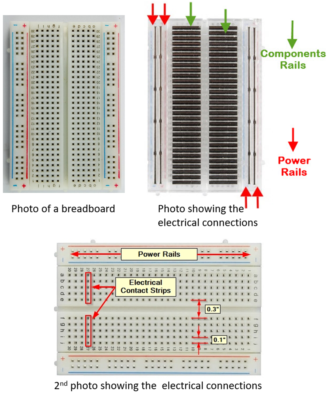
Refer to the breadboard illustration in the (Appendix Figure 5) to familiarize yourself with the breadboard layout and use the DMM on the continuity setting (Figure 1) to confirm the connections.
- Probe several connections to see whether they are connected or not. Do you see a pattern?
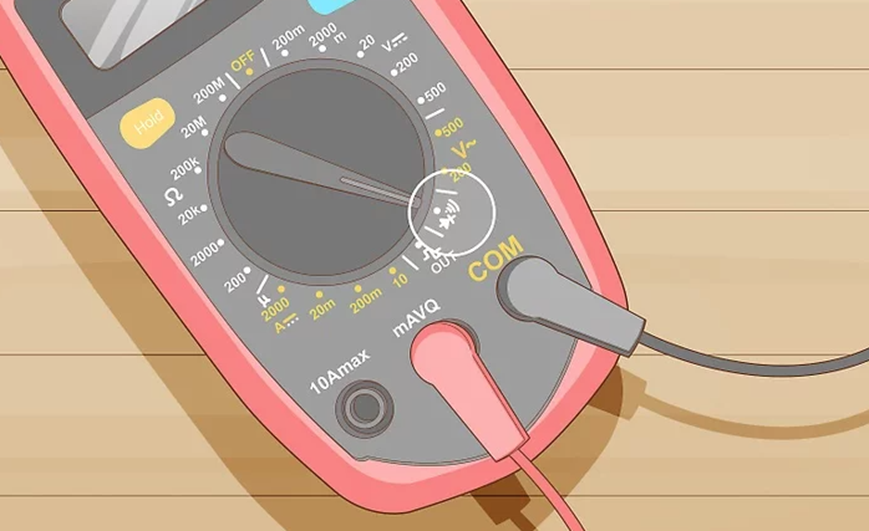
Set the DMM to read ohms (Ω) and make sure that you have plugged the cables into the correct outlet. When the DMM is set on Ω, never insert it into a circuit! Measure the actual resistance of your resistors and compare them to the values obtained in Step 1.
TipQuestion:Compare the nominal values that you read in the guide to your measurement. Did you read the nominal values from the guide correctly?
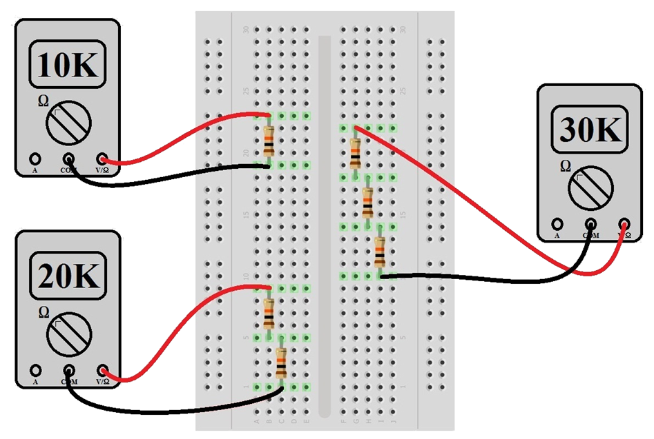
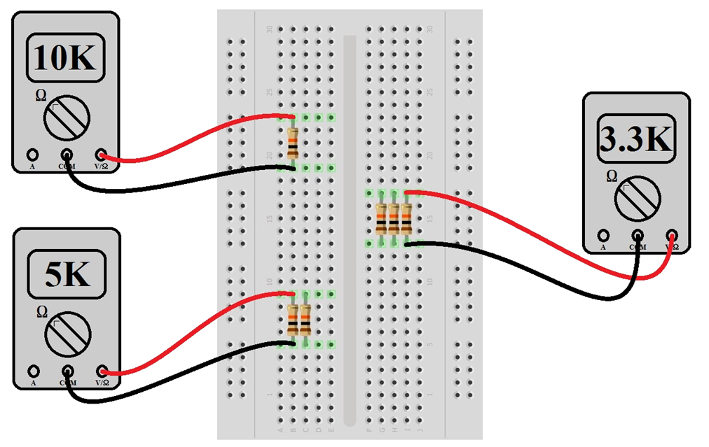
Refer to the figure “Measuring Resistance values using 10K Ohm resistors in series” (Appendix: Figure 6) to measure the resistance of several resistors in series.
- What are the individual resistances of the resistors you placed in series?
- What do you notice about the total resistance of the resistors in series?
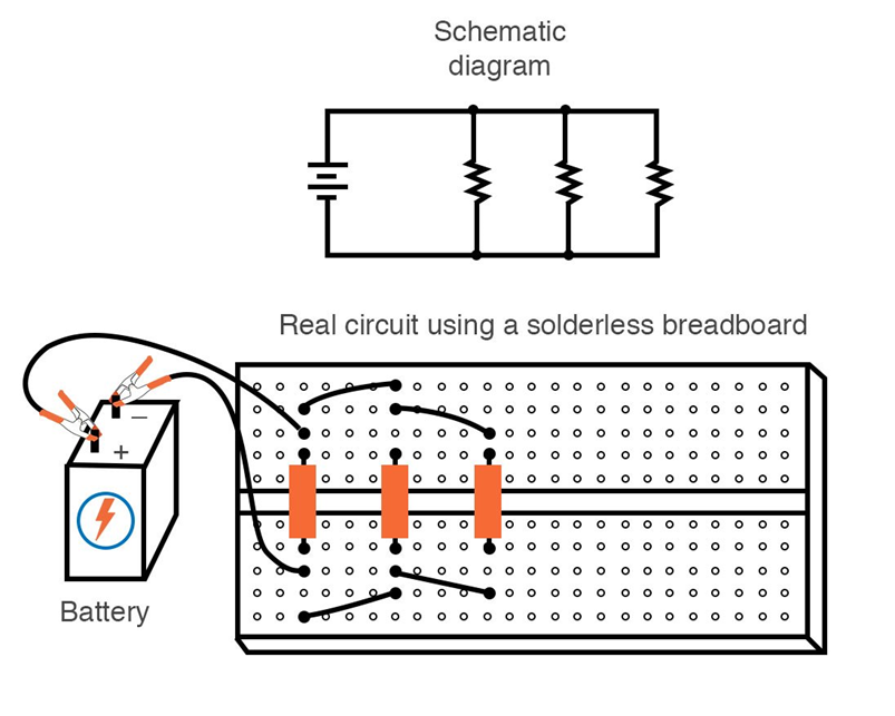
Refer to the figure “Measuring Resistance values using 10K Ohm resistors in parallel” (Appendix: Figure 7) to measure the resistance of several resistors in parallel.
- What are the individual resistances of the resistors you placed in series?
- What do you notice about the total resistance of the resistors in series?
Compare the total resistances of steps 4 and 5 and think about what this means for circuits. It may also be a good idea to review this a bit from your ISAT 152 notes …
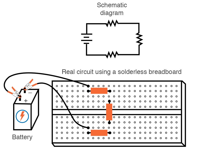
Build a small circuit by connecting an LED and a resistor in series. Make sure that you include a resistor, otherwise the current from the battery will fry your LED.
Have an instructor check your circuit and connect the 9V battery to power the circuit.
NoteThe long pin of the LED needs to be connected to the (+) lead of the battery
Think about your resistance measurements and the circuit you built: Do you think the power outlets in your apartment/ room are in series or in parallel? Why?
Working with the Raspberry Pi
The Raspberry Pi is a small, inexpensive ($35) computer that was originally produced in 2009 by the Raspberry Pi Foundation to help teach students basic computer science. It was originally intended to help developing nations that could not afford computers.
Your Pi runs a Linux operating system with a graphical user interface similar to a Windows PC or Mac.
Start the Raspberry Pi by connecting the power cable (and any other cables that might be missing).
The Connect the Raspberry Pi to the
JMU-Visitorwifi network. Dr. Gerken will share login credentials with you. You will need to open theweb-browserto complete the sign-in. Navigate towww.google.comand your browser will likely warn you of an insecure connection. This is fine, go to advanced and accept the connection to wifi sign-in window.NoteSometimes, the Pi will refuse to connect to the wifi. This is likely because the Pi was not used since last Spring. As a consequence the Pi forgot the correct date and time, which is checked when connection to the network.
To fix this, we can manually set the date and time in the terminal (change this to the correct date and time):
sudo date -s "2025-10-08 13:04:00"Keeping files and folders organized is important. Open the
Terminal(also on the top left of the screen) and create a new folder namesISAT_Labsin your home directory, navigate into the folder and create another folder namedLab0.You will see a prompt like this
~$that allows you to enter commands.The command to create a folder is
mkdirfollowed by the folder name.You change directories with the
cdcommand followed by the target folder.~$ mkdir ISAT_Labs ~$ cd ISAT_Labs ~/ISAT_Labs $ mkdir Lab0NoteLinux commands have the general structure of a command like
cdfollowed by one or severalargumentsseparated by spaces. See the examples formkdirorcdabove.You can check the terminal cheat sheet on the resource page for more handy terminal commands.
ImportantTo keep ourselves organized, you will create a new folder for each new lab. This folder should contain all your work. Make sure to save any files using descriptive names.
Write your first program:
ImportantThis and the next step require a working python-3 installation, which should come as a standard with the Pi. You can confirm that by checking whether the lower window of Thonny shows something like:
Python 3.9.2. (/usr/bin/python3)Check with your instructor, if you don’t see this. Or if the first python program does not run.
Open the Thonny Python Integrated Development Environment (IDE). You can find it in the
Programmingtab on thePi-StartThonny menu in the top left corner.You can also start it from the terminal like this:
~$ thonnyWrite your first Python program on the Raspberry Pi and check whether the python installation is working properly.
It is custom to start with a very simple program that will print out some text.
Type or copy the below text into the editor.
print('Hello ISAT 300')Save the file with the name
hello_isat.pyinto theLab0folder.Click the
playbutton and check whether your program worked andHello ISAT 300is printed into the shell window below.
Next we will do something a bit more interesting. We will use the PI to switch on and off an LED.
ImportantIn addition to a working Python3 installation, the next program also requires you to import the
RPi.GPIOmodule.If running the program produces an error message like this
Traceback (most recent call last):
 File"<string> ...
ModuleNotFoundError: No module named 'RPi.gpio'
we need to install the
RPimodule first. Your instructor can help with this.Your Pi is equipped with General Purpose Input and Output pins (GPIO) that enable easy communication with external sensors and controllers.
Connect the LED to the RPi as shown in the diagram below (Figure 2)
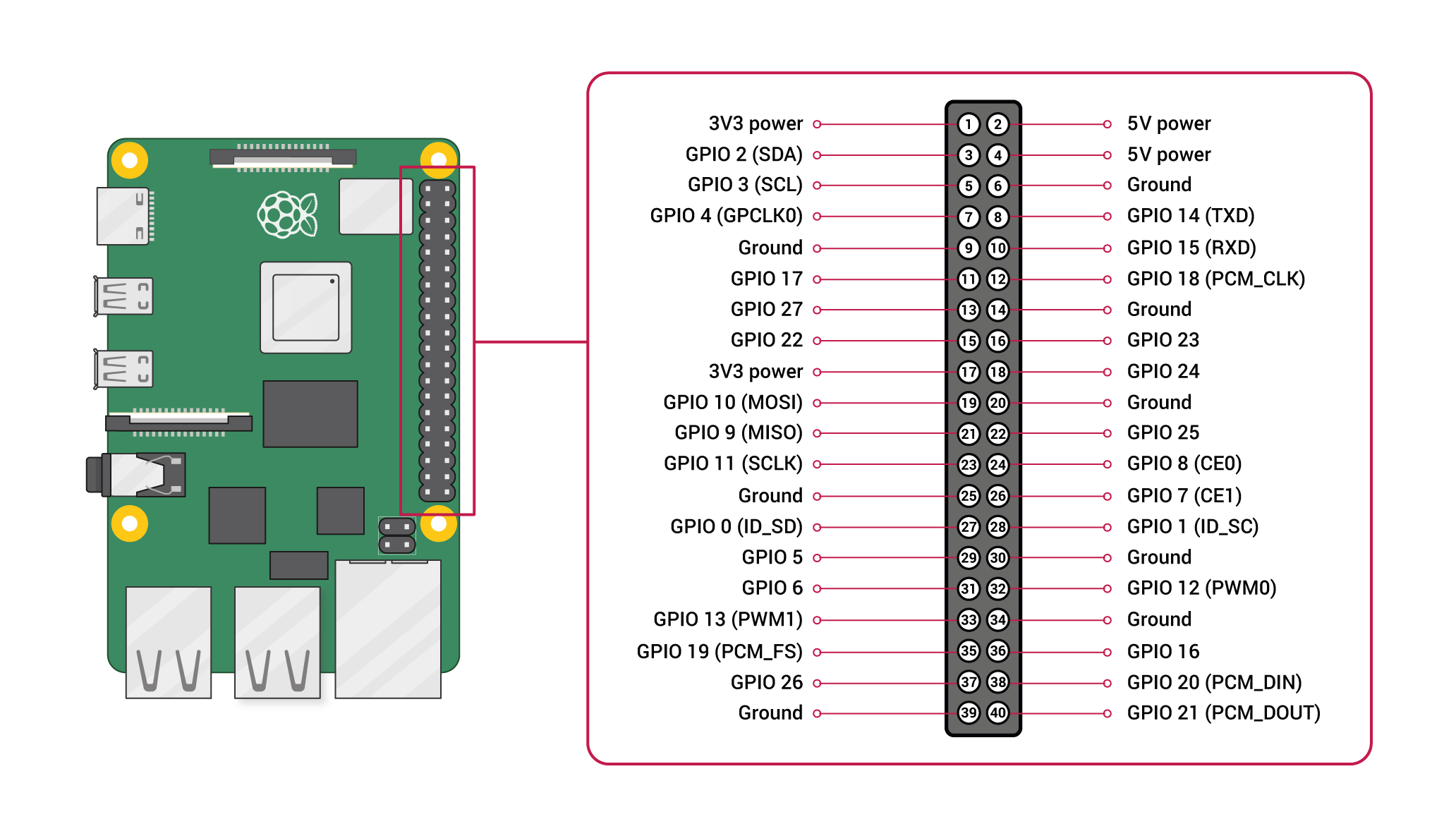
Figure 2: GPIO pin configuration and numbering, Credit: Raspberry Pi Ltd, CC BY-SA 4.0 NoteGPIO = General Purpose Input / Output –used to connect external devices (we will use these in this lab). ANY of the pins with GPIO designation could be used to operate the LED.
Switch off the Raspberry Pi and wire the LED as shown in the figure below (Figure 3).
WarningAlways switch off the Raspberry Pi before connecting and disconnecting wires from the GPIO.
Always have an instructor check your wiring before switching it back on, or otherwise you might damage the Pi or the sensors.
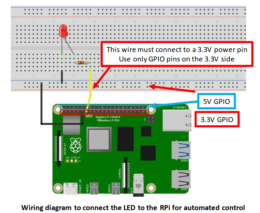
Figure 3: Wiring diagram for LED connection Have an instructor check your work and switch the PI back on.
Download and save the python program to the
Lab0folder.Run the program and see whether the LED lights up. The LED light might be very faint and you might need to shield it with your hand to see (or you might have the LED connected the wrong way around).
Remember back to your programming class and create a loop that makes the LED blink several times. Below is an example of a for loop with will execute 10 times. What needs to happen for the LED to blink?
    for i in range(10):
        <do something>
Look at the program line by line and try to understand what each line is doing.
Deliverables
There is no deliverable for this week.
There are no deliverables for today, but you will see all of the things done today again and again and your lab experience will be much smoother if you remember how to do them. This is also a good time to review some of your python coding.
Here are some things that you should know or know how to do:
- Build simple circuits of resistors in series or parallel
- Measure resistance of a resistor in a circuit
- Navigate the Raspberry Pi to open Thonny
- Create folders using the command line
- Write and execute a simple program on the Pi
Acknowledgements
Special Thanks for Chris Bachman for putting together the Appendixes.
Appendix 1 Resistors
Function
Resistors restrict the flow of electric current; for example, a resistor is placed in series with a light-emitting diode (LED) to achieve a certain specific current passing through the LED. Resistance is measured in ohms, and the symbol for ohm is an omega (Ω). One Ω is very small, so resistor values are often given in kΩ or MΩ: 1 kΩ = 1000 Ω and 1 MΩ = 1000000 = 106 Ω).
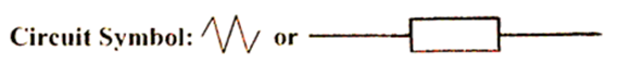
Resistors are indicated in circuit diagrams as:
Resistor values - the resistor color code
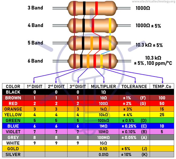
Resistor values are normally shown using colored bands. Each color represents a number as shown in the table. Most resistors have four bands:
The first band gives the first digit of the resistance.
The second band gives the second digit of the resistance.
The third band indicates the number of zeros after the 2nd digit.
The fourth band is used to show the tolerance of the resistor; that is, the ±% deviation from the nominal value of the resistor.
If there are five bands, then the first three bands give the first, second and third digits, the fourth band gives the number of zeros after the third digit, and the fifth band gives the tolerance of the resistor.
Examples of different resistors with different numbers of bands and color chart for decoding resistor values (note the multiplier can be either in the 3rd or 4th position)
Appendix 2: Breadboard Basics
We will use these in several labs.
Resistors in Series
Resistors in Parallel
History
| Revision | Description | Author |
|---|---|---|
| 2026-01-20 (S26) | Annual Update adding figure-alt-text and revision for clarity | Tobias Gerken |
| 2025-01-29 (S25) | Added warnings about python installation | Tobias Gerken |
| 2025-01-21 (S25) | Annual Revisions | Tobias Gerken |
| 2024-01-15 (S24) | Updated to Web and Extension with Pi Activities | Tobias Gerken |
| Initial Word Version | Tobias Gerken |